基于TMS320C5515設計的心電圖(ECG)MDK開發技術

• Embedded JTAG controller
• Color LCD display
• Keys (user switches)
The EVM operates from a + 5 V external power supply or battery and is designed to work with TI’s Code Composer Studio™ integrated development environment (IDE). Code Composer Studio communicates with the EVM board through the external emulator, or on-board emulator.
2)ECG Front-End Board
Figure 3 shows the ECG front-end board. The potentials captured by the electrodes are passed through
the defibrillator protection (DP) circuit in the ECG front-end board. Then, the front end board derives 8 out
of 12 ECG leads and provides the digital input to the DSP subsystem. The front-end board can be
interfaced with the EVM board through a universal front-end connector. The front-end board is interfaced
with and powered by the C5515 EVM board through the universal front-end connector by using I2C and
I2S interfaces.
The 16 channel analog-to-digital converter (ADC) (ADS1258) on the front-end board is configured for 500
Hz sampling with 24-bit data resolution. ADC is interfaced with the C5515 using the SPI bus.
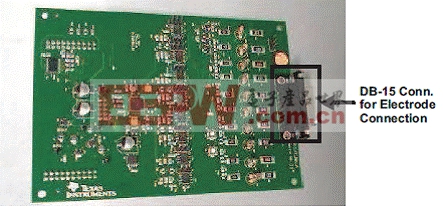
圖3。ECG板外形圖
3)ECG Cable
The ECG cable consists of four limb and six chest electrodes. This cable is connected to the front-end board through the DB15 connector. The ECG electrodes pick up ECG signals from the ECG simulator/patient and send them to the ECG front-end board; an off-the-shelf ECG cable is used. For more details regarding ECG cable
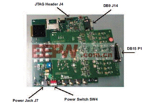
圖4。安裝在C5515 EVM的ECG前端外形圖
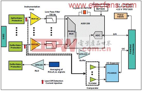
圖5。ECG 前端方框圖
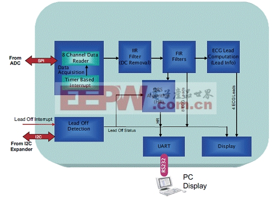
圖6。DSP軟件架構圖
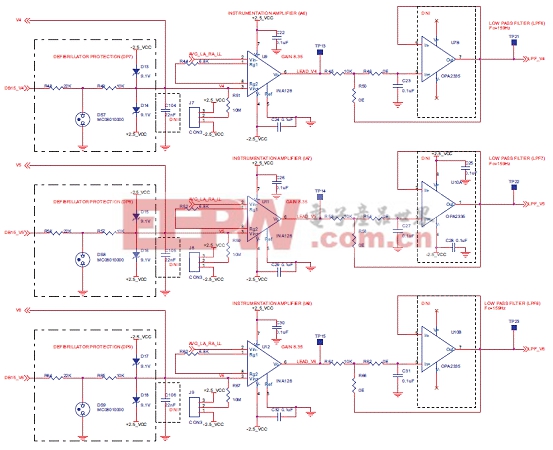
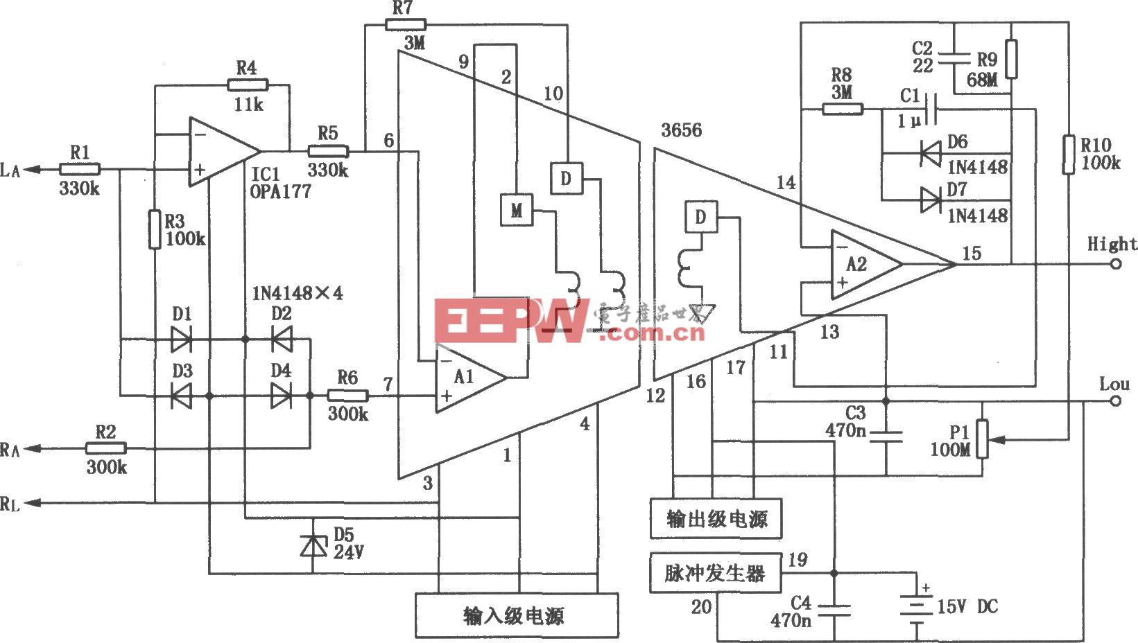
前端板電路圖
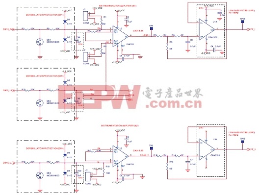
圖7。前端板電路圖:ECG_I_II
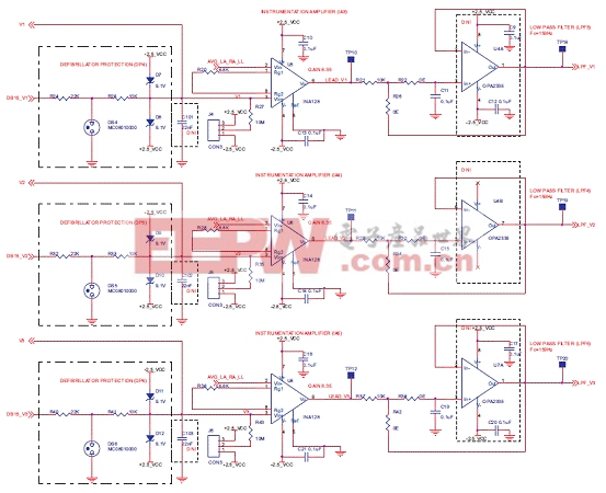
圖8。前端板電路圖:ECG_LEAD_V1_V2_V3


評論