狀態機“毛刺”的產生及消除措施

隨著EDA技術的高速發展, 以大規模和超大規模器件FPGA/CPLD為載體、以VHDL(硬件描述語言)為工具的電子系統設計越來越廣泛。有限狀態機(簡稱狀態機)作為數字系統控制單元的重要設計方案之一,無論與基于VHDL語言的其他設計方案相比,還是與可完成相似功能的CPU設計方案相比,在運行速度的高效、執行時間的確定性和高可靠性方面都顯現出強大的優勢。因此狀態機在數字電子系統設計中的地位日益凸顯。
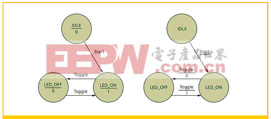
本文引用地址:http://www.j9360.com/article/148615.htm狀態機通常包含主控時序進程、主控組合進程和輔助進程三個部分。其中,主控組合進程的任務是根據外部輸入的控制信號和當前狀態的狀態值確定下一狀態的取向,并確定對外輸出內容和對內部其他組合或時序進程輸出控制信號的內容。一方面,由于有組合邏輯進程的存在,狀態機輸出信號會出現毛刺——競爭冒險現象;另一方面,如果狀態信號是多位值的,則在電路中對應了多條信號線。由于存在傳輸延遲,各信號線上的值發生改變的時間則存在先后,從而使得狀態遷移時在初始狀態和目的狀態之間出現臨時狀態——毛刺。
例如,采用Moore型有限狀態機方案對ADC0809采樣過程實現控制,其主要程序如下:
begin
lock =lock1;
process(current_state,eoc)
begin
case current_state IS
when st0=>ale=‘0’;start=‘0’;oe=‘0’;lock1=‘0’;
next_state =st1;
when st1=>ale=‘1’;start=‘0’;oe=‘0’;lock1=‘0’;
next_state =st2;
when st2=>ale=‘0’;start=‘1’;oe=‘0’;lock1=‘0’;
next_state =st3;
when st3=>ale=‘0’;start=‘0’;oe=‘0’;lock1=‘0’;
if (eoc=‘1’) then next_state =st3;
else next_state =st4;
end if;
when st4=> ale =‘0’;start =‘0’;OE=‘0’;lock1=‘0’;
if (eoc =‘0’) then next_state =st4;
else next_state =st5;
end if;
when st5=> ale =‘0’; start =‘0’;oe=‘1’;lock1=‘0’;
next_state =st6;
when st6=> ale =‘0’; start =‘0’; oe =‘1’;lock1=‘1’;
next_state =st0;
when others=> ale =‘0’; start =‘0’;oe =‘0’;lock1=‘0’;
next_state =st0;
end case;
end process;
process (clk)
begin
if (clk’event and clk =‘1”) then
current_state =next_state;
end if;
end process;
process(lock1)
begin

評論